What is an isotropic radiator?
An isotropic radiator is a hypothetical lossless point-source reference that radiates equally in all directions.
Amateur Extra · correct answers only, in question-pool order.
An isotropic radiator is a hypothetical lossless point-source reference that radiates equally in all directions.
Subtract the 2 dB feed-line loss and 2.2 dB duplexer loss from 7 dBd antenna gain, leaving +2.8 dB. Applying that gain to 150 watts gives about 286 watts ERP.
Effective radiated power expresses the resulting radiated power after antenna gain and system losses are taken into account.
Changing antenna height changes its electromagnetic interaction with ground and surroundings, which can change feed-point impedance.
Ground reflections can reinforce radiation in some directions, creating an apparent gain contribution from the antenna environment.
The listed losses total 8 dB and antenna gain is 10 dBd, leaving +2 dB net gain. Two hundred watts increased by 2 dB is about 317 watts ERP.
The losses total 6 dB and antenna gain is 7 dBi, leaving +1 dB net gain. Two hundred watts increased by 1 dB is about 252 watts EIRP.
Fresnel-zone radius decreases as wavelength decreases, so the highest listed frequency, 5.8 GHz, has the smallest first Fresnel zone.
Efficiency compares the resistance that represents useful radiation with the total resistance, including loss resistance.
A radial system reduces ground-loss resistance and provides a better RF return path for a ground-mounted vertical.
The conductivity of the surrounding soil determines how much RF energy is lost in the ground system.
A half-wave dipole has about 2.15 dB gain over isotropic, so subtracting 2.15 dB from 6 dBi gives 3.85 dBd.

The half-power points in Figure E9-1 span about 50 degrees.

Comparing the forward maximum with the response directly behind the antenna in Figure E9-1 gives an 18 dB front-to-back ratio.

The difference between the forward peak and side response in Figure E9-1 is 14 dB.

The plotted forward peak and rear response in Figure E9-2 differ by 28 dB.

Figure E9-2 plots antenna response as a function of elevation angle rather than compass direction.

The main lobe in Figure E9-2 reaches maximum response at about 7.5 degrees elevation.
A lossless directional antenna and a lossless isotropic radiator driven with equal power radiate the same total power; gain is produced by concentrating it in selected directions.
In the far field, the angular radiation pattern has stabilized and no longer changes shape as distance increases.
Method of Moments is a numerical electromagnetic technique widely used to model current and impedance on wire antennas.
The method models a wire as a series of small segments, each treated as having a uniform current value for the numerical solution.
Using fewer than about ten segments per half-wavelength can make the numerical representation too coarse and produce inaccurate feed-point impedance.
Two quarter-wave verticals spaced one-half wavelength and fed 180 degrees out of phase produce a figure-eight pattern oriented along the array axis.
Two quarter-wave verticals spaced one-quarter wavelength and fed 90 degrees out of phase combine into a cardioid pattern.
Two quarter-wave verticals spaced one-half wavelength and fed in phase produce a figure-eight pattern broadside to the array axis.
As an unterminated long wire becomes electrically longer, additional lobes form and the major lobes move increasingly toward the wire axis.
Moving the feed point away from center can produce useful feed-point impedances on several harmonically related bands.
The terminating resistor absorbs energy traveling toward the far end, suppressing the reverse lobe and making the pattern more unidirectional.
A conventional two-wire half-wave folded dipole has a center feed-point impedance of roughly 300 ohms.
A folded dipole uses a second parallel conductor connected at the ends of the half-wave element.
The G5RV uses a center-fed wire element and a specified length of balanced line before the transition through a balun to coax.
The classic Zepp antenna is an end-fed half-wavelength dipole.
Seawater's high conductivity improves reflection and reduces ground loss, increasing low-angle radiation compared with ordinary soil.
The Extra pool defines an extended double Zepp as a center-fed antenna about 1.25 wavelengths long.
As antenna height increases, the lowest elevation lobe generally moves to a lower takeoff angle.
A long descending slope can lower the apparent horizon and shift the main lobe to a lower takeoff angle in the downhill direction.
For an ideal parabolic reflector of fixed size, gain scales with the square of frequency. Doubling frequency therefore increases gain by a factor of four, or 6 dB.
Two Yagis on the same axis with perpendicular elements and coincident driven elements produce circular polarization when fed 90 degrees out of phase.
Placing the loading coil near the center puts it where antenna current is relatively high, improving radiation efficiency compared with base loading.
A high reactance-to-resistance ratio means the coil provides the needed inductive reactance with relatively little resistive loss.
The driven element of a conventional Yagi is approximately a half wavelength long.
Inductive loading raises antenna Q, so the usable SWR bandwidth decreases.
Top loading places more current higher on the radiator and can reduce the amount of lossy series inductance needed.
As Q increases, the antenna becomes more frequency selective and its low-SWR bandwidth decreases.
An electrically short antenna is capacitive; adding inductive reactance resonates it by cancelling that capacitive reactance.
As a base-fed whip becomes electrically shorter relative to wavelength, its radiation resistance falls.
With normal element spacing, a reflector provides more useful gain than using a director as the sole parasitic element.
Making parasitic elements longer or shorter than resonance changes their current phase, which shapes the directional pattern.
A beta or hairpin match works with a driven element that must be insulated from the boom.
A gamma match connects the coax shield to the driven-element center and the center conductor to an offset point through the gamma section.
A stub match uses a short section of transmission line connected in parallel near the feed point to cancel reactance and transform impedance.
The gamma rod introduces inductive reactance, and the series capacitor is adjusted to cancel it.
The beta or hairpin system supplies inductive susceptance, so the driven element is made electrically short and therefore capacitive.
A quarter-wave transformer uses Z = √(100×50) ≈ 70.7 ohms. Of the listed choices, 75 ohms is suitable.
Reflection coefficient describes the amplitude and phase relationship between the incident and reflected waves caused by a load mismatch.
A Wilkinson divider provides equal power division while maintaining a 50-ohm input and isolation between output ports.
A gamma-style shunt feed lets a grounded tower remain at DC ground while coupling RF into it near the base.
Feeding multiple driven elements through controlled phasing lines changes how their fields add and therefore shapes or steers the radiation pattern.
Velocity factor is the ratio of propagation velocity in the transmission line to the speed of light in vacuum.
The dielectric constant of the insulating material strongly determines wave velocity and therefore velocity factor.
Because electromagnetic waves travel more slowly in coax than in free space, a given physical length represents more electrical phase.
A half-wavelength transmission line repeats its terminating impedance at the input, so a short circuit appears as a short.
Microstrip is a printed conductor above a ground plane whose dimensions are chosen to behave as a controlled-impedance microwave transmission line.
An air-insulated half wavelength is approximately c/(2f). At 14.10 MHz this is about 10.6 meters.
Open-wire or parallel line has little dielectric loss and is commonly lower loss than comparable plastic-dielectric coaxial cable.
The official E9F08 source identifies lower safe maximum operating voltage as one significant difference of foam dielectric coax compared with solid dielectric coax.
The official E9F08 source identifies lower loss per unit length as a significant difference of foam dielectric coax.
The official E9F08 source identifies higher velocity factor as a significant difference of foam dielectric coax.
A quarter-wave line inverts the terminating impedance, so a short circuit appears as a very high impedance at the input.
A short-circuited line shorter than a quarter wavelength presents inductive reactance at one-eighth wavelength.
An open-circuited line shorter than a quarter wavelength presents capacitive reactance at one-eighth wavelength.
A quarter-wave line inverts the termination, so an open circuit appears as a very low impedance at its input.
A Smith chart graphically transforms normalized impedance as you move along a transmission line.
The Smith chart is built from families of constant-resistance circles and constant-reactance arcs.
Transmission-line impedance and standing-wave ratio are among the most common quantities determined with a Smith chart.
The basic Smith chart is formed by constant-resistance circles and constant-reactance arcs.
By moving along the chart and following constant-SWR circles, a designer can determine where a stub should go and how long it should be.

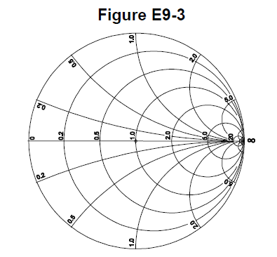
On the Smith chart in Figure E9-3, the reactance arcs terminate at the large outer circle called the reactance axis.

The horizontal resistance axis is the only straight line in the Smith chart figure.
Normalization sets the chart's center, or prime center, equal to the system characteristic impedance.
A constant-SWR circle shows all impedances having the same reflection-coefficient magnitude and is useful while moving along a line or designing a match.
The curved arcs on a Smith chart represent points having the same normalized reactance.
The peripheral scales are calibrated in fractions of transmission-line electrical wavelength for movement toward generator or load.
A Beverage receiving antenna achieves its characteristic directive traveling-wave behavior when it is long compared with wavelength; the pool specifies at least one wavelength.
Receiving directivity factor compares the antenna's peak gain with its average gain over the hemisphere around and above it.
An electrostatic shield reduces unbalanced electric-field coupling to nearby objects, preserving the loop's magnetic response and deep nulls.
A simple small loop has two opposite null directions, so an additional sense mechanism is needed to resolve the 180-degree ambiguity.
The proper termination approximates the antenna's traveling-wave impedance, producing relatively stable SWR across the desired frequency range.
The terminating resistor absorbs the traveling wave arriving from the far end and suppresses the rear response.
Adding a sense antenna combines an omnidirectional component with the loop response to resolve the 180-degree ambiguity.
Proper termination makes a pennant or similar loop unidirectional, producing a cardioid receiving pattern.
Increasing loop turns or enclosed area increases magnetic flux linkage and therefore increases induced output voltage.
A cardioid pattern has a single null, making direction finding easier because there is no opposite-direction ambiguity.